Conductor Size
Calculating conductor size is very important to the electrical and mechanical properties of a bus bar. Electrical current-carrying requirements determine the minimum width and thickness of the conductors. Mechanical considerations include rigidity, mounting holes, connections and other subsystem elements. The width of the conductor should be at least three times the thickness of the conductor.
Additions of tabs and mounting holes change the cross-sectional area of the conductor, creating potential hot spots on the bus bar. The maximum current for each tab or termination must be considered to avoid hot spots.
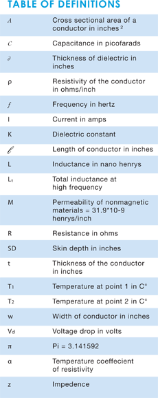
Cross-sectional area and the length determine bus bar conductor size. Cross-sectional area (..4) is equal to conductor thickness (t) multiplied by conductor width (w).
A value of approximately 400 circular mils per ampere is a traditional basis for design of single conductors. Since bus bars are not round, circular mils must be converted to mils squared (simply multiply the circular mils value by 0.785).
The following formula determines the minimum cross-sectional area of a conductor. This area should be increased by five percent for each additional conductor laminated into the bus structure. This extra five percent is a safety factor compensating for the compounding heat gain within the conductors.
This equation calculates the minimum cross-sectional area necessary for current flow:

A = Cross-sectional area of the conductor in inches²
l = Max DC current in amperes
N = Number of conductors in the bus assembly
To calculate the cross-sectional area of an AC current source, you must take frequency into consideration (See the section on Skin Effect).
Note: This formula has a breakdown point at approximately 300 amps of current. For calculations involving larger currents, we suggest you contact a Mersen engineer and refer to the ampacity table. In addition, you can find ampacity charts and comparative graphs at the Copper Development Association’s website, copper.org.

Capacitance
Capacitance of the bus arrangement depends upon the dielectric material and physical dimensions of the system. Capacitance varies only slightly with frequency change, depending on the stability of the dielectric constant. This variation is negligible and therefore is omitted in this analysis:

Increased capacitance results in a decreasing characteristic impedance. Low impedance means greater effective signal suppression and noise elimination. It is therefore desirable to develop maximum capacitance between conductor levels. This may be achieved by:
- keeping the dielectric as thin as possible, consistent with good manufacturing and design practices.
- using dielectrics having a high relative permitivity (k factor)
Skin effect
Because of skin effect phenomena, inductance and resistance are dependent on frequency. At high frequency, currents tend to flow only on the surface of the conductor. Therefore the depth of penetration of the electromagnetic energy determines the effective conducting volume.
The skin depth is given by:

For copper:

As frequency increases, inductance decreases to a limiting value, whereas the resistance increases indefinitely as the frequency approaches infinity.
Inductance
Maintaining a low inductance results in a low characteristic impedance and greater noise attenuation. When minimum inductance is a design objective, consider these tips:
- Maxomize the dielectric thickness
- Maximize the conductor width
- Increase the frequency
There are two types of inductance to be determined: internal inductance, which is a result of flux linkages within a conductor, and external inductance, which is determined by the orientation of the two current carrying conductors.
Distribution of current throughout a conductor at high frequencies is concentrated near the surfaces (called the “skin effect”). The internal flux is reduced and it is usually sufficient to consider only the external inductance. At low frequencies, however, the internal inductance may become an appreciable part of the total inductance. The formula for calculating the internal inductance at a low frequency is extremely lengthy and thus omitted in this analysis.
The formula for external inductance is:

High-Frequency Inductance (t>SD)

Resistance
To calculate the DC conductor resistance, the following formula applies (Resistance at 20°C):

To determine DC conductor resistance at temperatures above 20°C, use this formula:

For high frequencies the skin depth is taken into consideration. The formula for AC resistance is:
For (t >2SD)

AC resistance at 20 degrees C

Voltage drop
As current travels across a conductor, it loses voltage. This is caused by the resistivity of the conductor. The losses are referred to as voltage drop. Use this formula to calculate the voltage drop across the conductors:

Impedance
In the design of laminated bus bars, you should consider maintaining the impedance at the lowest possible level. This will reduce the transmission of all forms of EMI (electromagnetic interference) to the load.
Increasing capacitance and reducing inductance are the determining factors in eliminating noise.
The formula for calculating characteristic impedance is:


